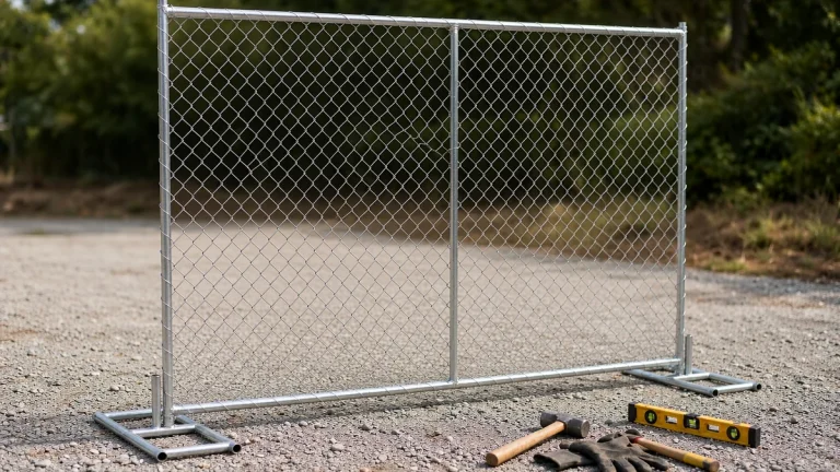
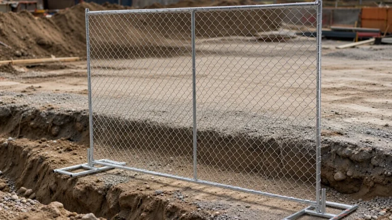
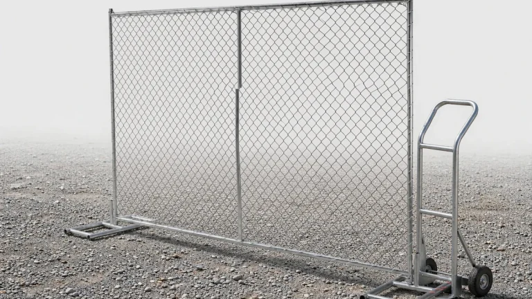
Install temporary fencing on concrete with a freestanding system designed for hard surfaces: mark the fence line and gates, clean the base positions, seat the panels in compatible weighted feet, clamp the joints, and fit the specified braces and ballast as you work. Keep every panel supported during assembly. Use bolt-down plates only when the owner permits drilling and the slab and anchor design have been checked.
The manufacturer’s installation plan determines the base arrangement, bracing, and ballast, not panel height alone. WorkSafe Victoria’s construction-site security guidance calls for fencing at least 1.8 m high, securely connected gates and joints, and stability under anticipated forces, including strong winds. Those are Victorian site-security recommendations, not a worldwide approval for any 6 ft fence.[1]
Choose a No-Drill or Anchored System
Freestanding feet avoid anchor holes, but they still need a suitable support layout. Confirm the panels, feet, clamps, braces, and ballast as one compatible system. Do not mix components unless the system supplier has confirmed their compatibility.
| Situation | Arrangement | Confirm |
|---|---|---|
| General slab, no drilling | Compatible freestanding feet, with braces and ballast where specified | Base mass and footprint, socket fit, clamp type, support layout, and wind suitability |
| Finished or coated floor | Non-penetrating feet with approved floor protection | Pad compatibility with the finish, contact pressure, and effect on the system’s stability |
| Anchored layout specified and drilling approved | Bolt-down feet or base plates with designed anchors and bracing | Slab suitability, embedded items, anchor selection, embedment, edge distances, and written permission |
Before Drilling the Slab
For rented premises, polished floors, parking decks, post-tensioned slabs, thin toppings, or an unknown slab, stop and obtain the owner’s permission and a competent assessment of the proposed fixings. Written permission alone does not establish that drilling is safe. Identify slab thickness and condition, reinforcement or tendons, and concealed services before choosing hole locations.
HSE’s HSG47 sets out planning, locating and identifying buried services, and safe excavation as the three elements of safe work near underground services. It is excavation guidance, not a method for clearing a concrete slab for drilling.[2] The slab investigation and anchor design must address the actual structure.
Follow the selected anchor’s instructions for hole diameter, depth, cleaning, embedment, edge distances, and tightening. Longer service life or wind exposure does not, by itself, make a bolt-down arrangement suitable.
Control silica dust when drilling concrete. In US construction work covered by OSHA 29 CFR 1926.1153, Table 1’s handheld and stand-mounted drill entry specifies a shroud or cowling with dust collection, manufacturer-recommended airflow, a filter at least 99% efficient with a cleaning mechanism, and a HEPA-filtered vacuum for hole cleaning. Follow the applicable exposure-control requirements; working outdoors is not a substitute for dust control.[3]
Mark and Prepare the Concrete
Mark the fence line, gate openings, corners, and each proposed foot position. Locate expansion joints, drains, curbs, steps, cracks, spalling, and repaired areas. Move feet away from unsupported edges and covers unless the support arrangement has been assessed. Each foot needs the bearing surface specified by the supplier, without rocking.
Remove grit and loose debris, and address oil or standing water before placing feet. On finished floors, agree pad material, contact-pressure limits, and cleaning methods with the owner. Check a sample pad on an inconspicuous area, but do not treat that check as proof that long-term marking cannot occur. Get supplier approval for pads that change the base’s contact with the floor.
Allow room for brace feet and ballast as well as the fence itself. Keep loading doors, hydrants, electrical cabinets, emergency exits, and vehicle sightlines clear. Where US ADA requirements apply, check the accessible route’s clearances and protruding-object limits under the 2010 Standards, including Sections 307 and 403; fence feet must not compromise the required route.[4] On sloping concrete, use an approved level-change arrangement rather than scrap shims.
Check Panel Sizes and Quantities
Haisen’s Canadian-style temporary fence panels are listed at a nominal 6 ft high, about 1.83 m, with the sizes below. Listed options include 3.0, 3.5, or 3.8 mm wire, 25 x 25 or 30 x 30 mm outer frames, and hot-dip galvanized or powder-coated finishes. These are ordering specifications, not concrete-installation or wind ratings. If choosing a chain-link temporary fence panel instead, confirm its own compatible feet and connections.
The metric dimensions and rectangular face areas below are calculated from nominal imperial sizes and rounded for purchasing reference. Face area is not the solid area of the mesh or a wind-load calculation. Confirm actual installed widths, including connection details.
| Nominal size | Approximate metric dimensions | Rectangular face area |
|---|---|---|
| 6 x 8 ft | About 1.83 x 2.44 m | 48 sq ft / about 4.46 m² |
| 6 x 9.5 ft | About 1.83 x 2.90 m | 57 sq ft / about 5.30 m² |
| 6 x 10 ft | About 1.83 x 3.05 m | 60 sq ft / about 5.57 m² |
A Worked Layout Check
Measure each run between its intended endpoints and subtract the gate opening. This hypothetical example uses nominal 10 ft panels and ignores connection allowances so the estimating arithmetic is easy to check.
| Example | Calculation | Layout consequence |
|---|---|---|
| 60 ft run, nominal 10 ft panels | 60 / 10 = 6 | Six panels in the simplified estimate; verify installed widths |
| Same run with 12 ft vehicle gate | (60 – 12) / 10 = 4.8 | Rounding up gives five panels for estimating, not an exact fit |
The gate example leaves 48 ft for panels. Five nominal 10 ft panels occupy 50 ft, which is 2 ft too much. Resolve that discrepancy with a supplier-approved short panel or revised layout before ordering. Do not assume panels can overlap, be cut, or extend past the agreed boundary.
Check support counts separately. In a straight, ungated layout with one shared foot at each joint and one at each end, six panels need seven feet. That is a layout calculation, not a universal product rule; corners, gate posts, and other base designs change the count. List clamps, braces, ballast, and gate hardware alongside the panels. The temporary fence installation planning guide covers the wider layout process.
Confirm Bracing and Ballast
There is no single ballast weight that follows from a panel being 6 ft high. Obtain the supplier’s support layout for the site exposure, run length, corners, gates, and any coverings. If those inputs are missing, do not guess a number of blocks or a wind rating.
WorkSafe Victoria warns that signage and shade-cloth coverings may require additional support against wind loading.[1] Have the covered configuration checked before attaching banners or privacy mesh. Use only the specified ballast locations and retain the required pedestrian clearances.
Install the Panels and Gates
- Place the starting feet. Orient their sockets as specified and check that they bear properly on the prepared concrete. Fit approved floor protection where required. Keep the assembly area clear of passing people and vehicles.
- Stand and stabilize the first panel. Use the handling method and crew specified for the panel. Keep it supported until the required starting braces, connections, and ballast are in place. Feet alone do not establish that an isolated panel is stable.
- Add panels and secure each joint. Seat each panel fully, fit the specified clamps or connectors, and tighten to the system instructions. Add braces and ballast progressively so the unfinished run remains supported. Recheck base seating after tightening.
- Complete the support layout. Check every specified end, corner, direction change, intermediate brace, and gate-post support against the plan. Do not substitute loose materials or remove a foot to make a bay fit.
- Hang and test the gates. Confirm the clear opening and swing direction before fitting the leaves. Check that each leaf clears feet, ballast, and surface rises, closes without lifting, and latches correctly. Secure open leaves against unintended movement. Where a gate serves an escape route, its security arrangements must preserve the required emergency egress.
Inspect Before Opening the Area
Walk both sides of the fence. Check for rocking feet, leaning panels, loose clamps, missing pins, displaced ballast, slipped braces, sharp wire, and obstructed routes. Confirm that gates and joints are secure and that gaps beneath the fence do not defeat the site’s security requirements. WorkSafe Victoria specifically calls for fencing that is difficult to climb and prevents access underneath.[1]
Record the inspection and any defects. Recheck after relocation, strong winds, or a vehicle strike, and at the intervals set by the site plan and supplier. Isolate a damaged or unstable section until a competent person has assessed and corrected it.
A hand check may reveal looseness or rocking. It does not establish wind resistance or replace the specified support design.
Remove Without Losing Support
- Exclude traffic from the work area and follow the supplier’s dismantling sequence. Keep the remaining fence stable while coverings and gate leaves are handled.
- Support the bay being removed before releasing its clamps, braces, or ballast. Do not strip support from the whole run first.
- Lift components clear rather than dragging them across the slab. Remove the remaining feet and ballast only when they are no longer needed for stability.
Collect debris using methods appropriate to the material; use the applicable silica controls for concrete dust. Report anchor holes, staining, or other damage, and use only the owner’s approved repair method. Store components as matched sets for the next installation.
Need panels, bases, and gates sized for a concrete slab?
Send your run lengths and gate widths for a project quotation.