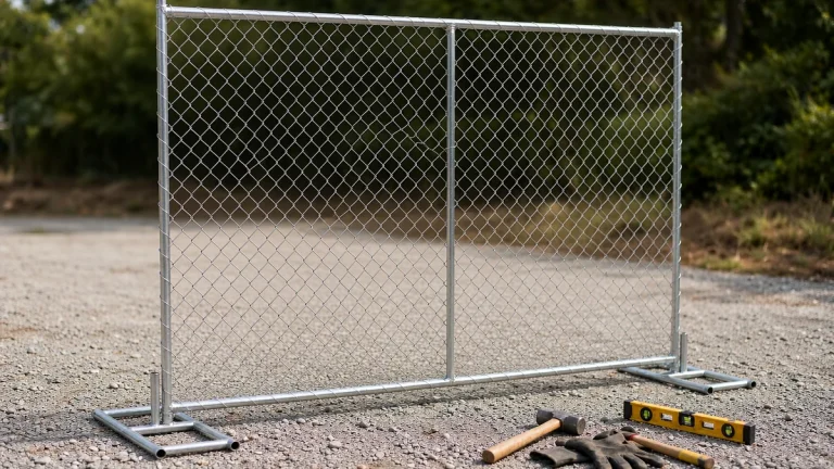
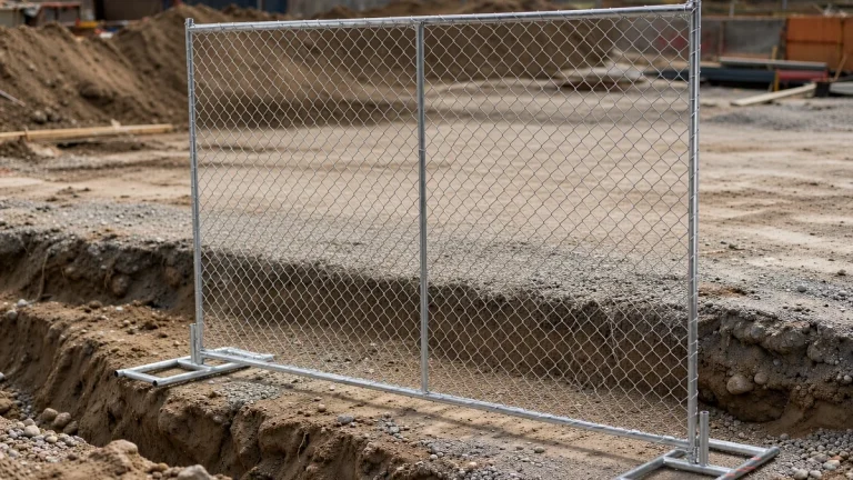
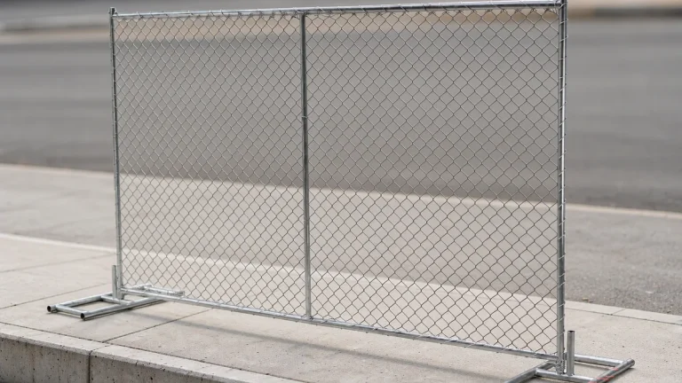
Yes, some temporary fencing can be installed by one person, but only when the system’s installation instructions and the site assessment support solo work. A short, straight run on firm, level ground in calm weather is a possible candidate. Being able to lift a panel is not enough: you must also be able to position, secure, and connect it without leaving it unsupported. If that needs another pair of hands, arrange help before unloading.
When solo installation is realistic
This guide covers freestanding mesh panels on matching feet. Consider working alone only when all of these conditions hold:
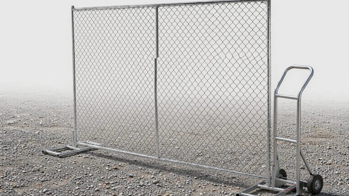
- The manufacturer’s installation method allows one person to handle and secure the components at every stage.
- You have the actual panel and base weights, and can handle each component with a secure grip and a clear view of the route.
- The ground is firm and level, the carry route is short and clear, and weather conditions are within the system’s limits.
- The specified feet, connectors, and supports are available and can be fitted safely without assistance.
- The site assessment permits lone work, with a way to obtain help if conditions change.
A gate, awkward corner, heavy ballast, or exposed location is a reason to reassess the job, not to omit the components that make it stable. For an unfamiliar system, ask the supplier to confirm the installation sequence and crew requirements.
On construction sites in Great Britain, HSE includes site fencing and hoarding within temporary works. Temporary structures must be designed, installed, and maintained to withstand foreseeable loads and used for their intended purpose. That duty does not specify a universal crew size or approve solo installation Temporary works.htm.
What makes panels hard to handle
Panel size and wind
The published Haisen temporary fence specifications list 6 ft-high panels in nominal lengths of 8, 9.5, and 10 ft. Their overall dimensions help explain the space needed to carry and turn them.
| Nominal panel size | Approximate metric size | Gross rectangular area |
|---|---|---|
| 6 × 8 ft | 1.83 × 2.44 m | 48 sq ft / 4.46 m² |
| 6 × 9.5 ft | 1.83 × 2.90 m | 57 sq ft / 5.30 m² |
| 6 × 10 ft | 1.83 × 3.05 m | 60 sq ft / 5.57 m² |
These areas are height multiplied by nominal length, with metric values rounded from square feet. A 6 × 10 ft panel has 25% more gross rectangular area than a 6 × 8 ft panel: (60 − 48) ÷ 48 = 25%. This is a size comparison, not a claim of 25% more wind load. Open mesh is not a solid sheet, and these figures provide no wind rating or safe wind-speed limit.
Adding privacy mesh, banners, or sheeting changes the assembly and its wind-loading requirements. Obtain a suitable support arrangement before fitting a covering; extra hands alone do not resolve an unsuitable fence design.
Weight and grip
Check the finished panel and base weights for the exact order. A weight from a different panel listing cannot establish whether you can handle your parts. A large panel may be awkward even when its mass seems manageable, particularly if it obstructs your view or leaves little room to turn.
HSE’s guidance for Great Britain states that the law does not set specific manual-handling weight limits. Employers must avoid hazardous handling where reasonably practicable, assess unavoidable hazardous handling, and reduce the risk of injury Index.htm.
Plan the lift, clear the route, use suitable handling aids where possible, and get help when unsure. Do not carry a panel along a route you cannot see. Set the load down safely before adjusting its position or grip Good handling technique.htm. OSHA’s ergonomics guidance also supports controlling handling hazards through changes to the task and workplace, rather than relying on lifting technique alone Ergonomics.
The first unsupported panel
The critical question is how the first panel stays secure while you fit the next component or tighten a connector. Standing a panel in feet does not, by itself, prove that it is stable. Neither does joining two or three panels.
If you must let go of an unsecured panel to fetch another part or use a tool, stop and arrange assistance or a manufacturer-specified support method.
Do not improvise a one-handed balancing method. The installation sequence must provide stability during assembly as well as after completion.
A worked solo-planning example
Panel count tells only part of the workload. These nominal calculations assume a straight run with no gates; they are planning examples, not tested solo-installation limits.
| Panel arrangement | Nominal coverage | Panel-to-panel joints |
|---|---|---|
| Five 6 × 8 ft panels | 5 × 8 = 40 ft | 4 |
| Five 6 × 10 ft panels | 5 × 10 = 50 ft | 4 |
| Seven 6 × 8 ft panels | 7 × 8 = 56 ft | 6 |
Five 10 ft panels provide 10 ft more nominal coverage than five 8 ft panels. Seven 8 ft panels total 56 ft nominally, so they cannot be assumed to fit an exact 50 ft boundary. Use the system’s effective installed width and account for transitions, corners, and gates; the panel size and coverage guide distinguishes these layout measurements.
- Feet: If the system shares one foot at each panel joint and uses one at each end, N panels need N + 1 feet. Five panels then need six feet, and seven need eight. Other systems use separate feet for each panel or additional supports; use their drawings instead.
- Clamps: Multiply the number of joints by the specified clamps per joint. Four joints would need eight clamps at two per joint, or twelve at three per joint. Six joints would need twelve or eighteen respectively. These are arithmetic alternatives, not permission to choose the clamp count. Clamp quantities must also account for any separate gate, brace, or end hardware.
- Carrying: Under the six-foot assumption, five panels plus six feet mean eleven loaded trips if each component is carried separately. That excludes tools, connectors, supports, return walks, and inspection.
Checking Haisen’s published product specification provides the nominal dimensions above, but not finished panel or base weights. Coverage can therefore be calculated from that page; solo handling cannot be confirmed from it. Request those missing weights and the installation method before committing to a one-person job. This worked example is a specification-based calculation, not a timed field installation.
Preparing a permitted solo installation
Confirm the layout
Draw the run, delivery position, carry route, ground changes, and all required supports before unloading. Include any gate opening even if a separate crew will fit it. The installation layout should show the complete system, not just the panels.
Ground type alone does not determine crew size. For installation on grass, assess the soil beneath the turf and the specified base or anchoring arrangement. For installation on concrete, confirm the feet, bracing, and ballast or anchor design. Firm concrete does not make an unsupported panel safe.
HSE’s Great Britain guidance calls for suitable physical site boundaries where necessary, with fencing planned, provided, and maintained. It also addresses the risk of pedestrians being struck by vehicles entering or leaving a site. Keep the assembly area and carrying route separated from those movements Publicprotection.htm.
Check parts before lifting
With the panels safely stored, inspect feet for damage and rocking, check sockets for obstructions, and confirm that connectors are compatible. For threaded clamps, check that threads engage correctly before a panel needs holding. A damaged foot or seized fastener should be dealt with while both hands are free.
Stage tools and connectors within reach without obstructing the route. Select gloves, protective footwear, and any eye protection for the task’s hazards. Keep children, pets, and bystanders outside the assembly area.
Follow the assembly sequence
- Position the specified feet and supports according to the manufacturer’s layout.
- Raise and secure the first panel using the prescribed method. Do not leave it unsupported while preparing the next panel.
- Add panels in the specified order, fitting all required connectors and supports as the run grows. A clamp connection does not replace a required brace or ballast.
- Check seating, alignment, and fastener tightness against the instructions before extending the run. Stop if positioning a panel and operating the tools cannot be done safely alone.
Do not substitute unspecified “light stabilizers” for required supports, omit ballast to reduce carrying, or drill anchors without the necessary design and site checks. If the approved sequence requires help, use that crew arrangement.
Secure pauses and completion
Before any break, leave the assembly in the stable condition specified for that stage. If that cannot be achieved, stop further erection and arrange a safe securing or dismantling method with competent help. Do not rely on improvised lashing or blocking, or leave loose panels leaning against a vehicle.
WorkSafe Victoria advises installing proprietary fencing to the manufacturer’s specifications and ensuring it can withstand anticipated loads, including strong winds. Signs and shade-cloth coverings may need additional support. These are Victorian guidance points, not a universal one-person installation approval Construction site security fencing.
Inspect the completed line for movement, loose connectors, sharp edges, and trip hazards. Investigate feet that slide, tip, sink, or rock rather than simply adding weight. Recheck after wind, rain, impact, or another relevant change, as required by the site plan and system instructions. Keep unused components in suitable storage and transport arrangements so they cannot fall or obstruct the working area.
When to arrange help
Use these as conservative planning triggers for assistance or a revised installation method, not as a statutory crew-size schedule:
- The instructions call for two installers, or you cannot keep a panel secure while connecting it.
- A temporary fence gate, corner, brace, anchor, or ballast arrangement creates a handling or support task you cannot manage safely alone.
- Panels, bases, or repeated carries cause strain, obscure your route, or require an awkward grip.
- The route includes steps, slopes, soft ground, traffic, or restricted turning space.
- Wind, screening, public access, or a nearby hazard requires a different design or working arrangement.
- Fatigue, poor visibility, or a deadline makes the planned method impractical.
A second person can help with handling and connections. They do not compensate for missing supports, unsuitable ground, or an unverified fence design.
Allowing enough installation time
No verified installation rate is available for this example. Estimate from the actual delivery position, component count, carry distance, assembly sequence, inspections, and rest breaks. The eleven-trip example explains why a small panel count can still involve substantial walking. Do not convert it into a minutes-per-panel promise or assume two people will halve the time.
The decision before unloading
One-person installation is a system-specific decision. Confirm the component weights, the method for securing the first panel, and the supports needed throughout assembly. If any of those answers is missing, obtain the information before starting. A short fence line is only a candidate for solo work, never proof that the job is safe to do alone.
Panel, foot, and clamp check
Share your run length, ground type, and gate plan. Haisen quotes the matching panels, feet, and connectors to specification.
References
- Health and Safety Executive (UK). Temporary Works.
- Health and Safety Executive (UK). Manual handling at work.
- Health and Safety Executive (UK). Good Handling Technique.
- Occupational Safety and Health Administration. Ergonomics.
- Health and Safety Executive (UK). Protecting the public.
- WorkSafe Victoria. Construction site security fencing.