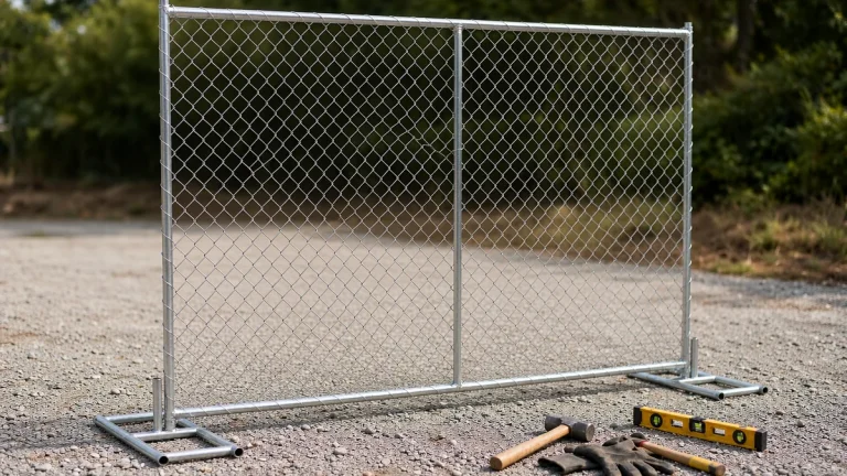
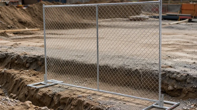
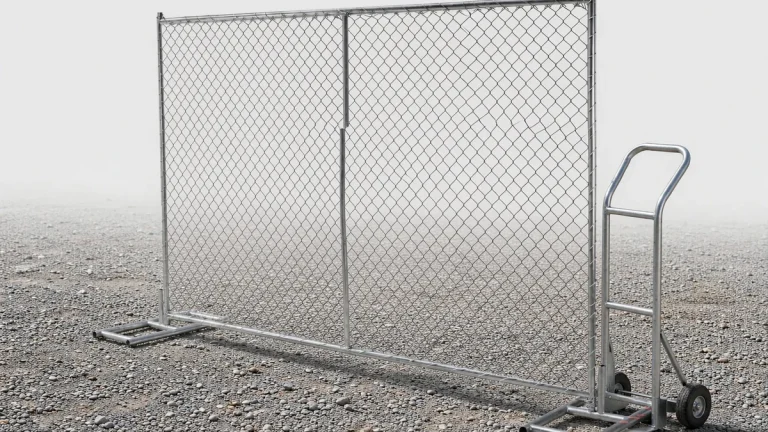
To install temporary fencing on asphalt without drilling, mark the fence line, sweep the base locations, and set a compatible freestanding panel system on fully supported feet. Connect and brace each section as it goes up, then place ballast exactly as the manufacturer specifies for the layout and wind exposure. Fit the gates and check connections, clearances, and pavement protection before opening the area.
Use a system approved for the site conditions, not loose panels held down with improvised weights. Fence height, base type, brace spacing, and ballast depend on the chosen system and local requirements; a 6 ft panel is an available product size, not a universal installation rule. Drilling or driving posts requires separate permission and a site-specific anchorage design.
Check the Asphalt First
Get the owner’s written conditions for drilling, ballast blocks, surface protection, marking materials, and repairs. Photograph existing cracks, patches, and stains before delivery so the starting condition is documented.
Walk the proposed line and avoid placing feet on potholes, loose or crumbling asphalt, soft patches, oil contamination, unsupported edges, drains, covers, or repaired cuts that cannot provide firm, even support. Flag slopes and places where water collects.
Mark runs, corners, gate openings, and the full footprint of feet, braces, and ballast with owner-approved removable markings. Keep emergency exits, hydrants, electrical cabinets, loading doors, and driver sightlines clear. Allow for vehicle turning and overhang, and keep supports outside required pedestrian routes.
Choose a No-Drill System
Match the panels, feet, connectors, braces, ballast, and gate supports to the manufacturer’s installation drawing. Do not assume parts from different systems are compatible because their dimensions look similar. If the project specifies chain-link temporary fence panels rather than welded mesh, confirm the support arrangement for that exact panel system.
WorkSafe Victoria’s construction-site security guidance calls for fencing at least 1.8 m high, securely connected gates and joints, installation of proprietary systems to manufacturer specifications, and stability under anticipated forces such as strong winds. It also notes that signage and shade-cloth coverings may need additional support. These are Victorian site-security recommendations, not an asphalt anchorage specification or a worldwide approval for any 6 ft fence [1].
| Situation | Installation approach | What to confirm |
|---|---|---|
| Sound, fairly level asphalt | Compatible freestanding feet with specified braces and ballast | Foot fit, base footprint, connector type, bracing layout, wind suitability |
| Sound, sealed asphalt | Freestanding system with approved surface protection | Pad compatibility, stain risk, and stable contact beneath the feet |
| Fresh, soft, or recently sealed asphalt | Wait or reroute until the pavement contractor accepts loading | Readiness for feet and ballast; pads alone do not establish suitability |
| Sloped or uneven asphalt | Approved level-change layout, or reroute | Permitted slope or steps, connector movement, and full base support |
| Drilled or driven fixing proposed | Separate site-specific anchorage design and written permission | Suitable anchorage substrate, pavement build-up, buried services, and repair plan |
Owner permission is not proof that an anchor will work. Do not apply a concrete-anchor detail to asphalt by default. A competent person must confirm the anchorage design and suitable substrate before any drilled or driven system is used. If neither an approved freestanding layout nor a suitable anchored design is available, do not erect the fence at that location.
Count Panels for the Asphalt Run
Measure each straight run separately, subtract its gate openings, and confirm the effective installed panel width, including connections. Plan corners, ends, and gates from the system drawing rather than treating them as ordinary straight-run joints.
Haisen lists its Canadian-style temporary fence panels at a nominal 6 ft high, in 8, 9.5, and 10 ft lengths, with 3.0, 3.5, or 3.8 mm wire and 25 × 25 or 30 × 30 mm outer frames. The following metric dimensions and face areas are calculated from those nominal imperial sizes and rounded for planning. Face area means height multiplied by length, not solid wind-catching area or a wind rating.
| Panel size | Approximate metric size | Panel face area |
|---|---|---|
| 6 × 8 ft | 1.83 × 2.44 m | 48 sq ft, about 4.46 m² |
| 6 × 9.5 ft | 1.83 × 2.90 m | 57 sq ft, about 5.30 m² |
| 6 × 10 ft | 1.83 × 3.05 m | 60 sq ft, about 5.57 m² |
For a planning example, 10 nominal 8 ft panels total 80 ft of panel length and create 9 panel-to-panel joints in one uninterrupted straight run. Connections can change the installed length, so 80 ft is not a guaranteed finished measurement. This example excludes gates and corners and does not determine the number of feet, clamps, braces, or ballast blocks.
Check the delivery against the drawing: panels, feet, connectors, braces, ballast, and complete gate assemblies. Bring a broom, tape measure, approved marking materials, gloves, the specified tools and lifting equipment, and any agreed protective pads. Set aside damaged or mismatched parts instead of forcing them together.
Install the Run Step by Step
- Prepare the base locations. Remove loose grit, gravel, glass, and standing water. Avoid contaminated spots unless the owner accepts a cleaning method and the cleaned surface is suitable for the system.
- Position the feet. Follow the drawing for spacing and orientation. Each foot needs firm, even support with no rocking or overhang. Use protective pads only where the manufacturer and pavement owner accept their material and placement.
- Secure the first panel. Seat it in its compatible feet and install the specified connections and initial supports. Follow the manufacturer’s erection sequence and temporary-support method; do not leave a panel standing unsupported.
- Connect the next panel. Fit and tighten connectors using the specified method before extending the run. Do not force a binding connection or leave loose joints for later.
- Add braces and ballast as the run grows. Install them at the locations and in the sequence shown, including the details for ends, corners, and gates. Do not build a long unsupported run and plan to stabilize it afterward.
- Fit the gate assembly. Use the specified supports, hinges, latch, stops, and hold-open arrangement. Do not cut a standard panel into a gate unless the manufacturer supplies an approved conversion.
- Check before handover. Compare the completed layout with the drawing, operate each gate, and inspect support contact, connectors, gaps, and access routes.
Check the First Bay Before Extending the Run
With the first bay secured according to the erection plan, inspect the actual setup. Do the feet sit evenly? Are connectors fully engaged? Do braces or ballast project into a walkway? Record the positions and any surface marks before repeating the layout along the run.
If a foot rocks, stop and check both the pavement and the component. Remove loose debris, inspect the foot for damage or mismatch, and use the approved correction or move the line. Extra ballast is not a substitute for proper base support. This check can catch a layout problem early, but it does not establish a wind rating.
Keep vehicles and bystanders away from the erection area. Follow the supplier’s weather limits and the site’s wind-response plan; do not use a worker’s ability to hold a panel as the safe-wind test. The National Weather Service warns that high winds can blow objects around and threaten safety [2].
Gates, Corners, and Slopes
Check gate width, posts, clearance, and swing direction against the temporary system’s gate drawing. Open and close the leaf through its full travel: it should clear the asphalt, latch correctly, and leave the supports seated. Fit the specified latch and hold-open devices without obstructing required emergency access.
Use the system’s corner and end details. A connector’s ability to turn through an angle does not, by itself, confirm that the corner is adequately supported.
Slopes and Drains
Use a stepped or racked arrangement only if the system permits it. Keep joints within their allowed movement and every foot fully supported; do not bridge a drain or balance a foot on a rounded curb. If the approved layout cannot follow the slope without binding connections or unacceptable gaps, reroute the fence. Recheck low spots after rain for ponding, debris movement, or displaced supports.
Wind and Surface Protection on Asphalt
There is no universal ballast weight for temporary fencing on asphalt. Obtain the manufacturer’s layout for the exact panel, base, fence height, exposure, and any coverings. Confirm brace positions, ballast quantities and placement, weather limits, and the response required before forecast severe weather. Do not treat a panel’s dimensions or a successful first-bay check as proof of wind stability.
Privacy screens, shade cloth, banners, and signs are additions to the fence, not the same thing as its original mesh infill. Leave them off unless the supplier approves the covered configuration and its support and weather-response requirements. Keep ballast in its assigned position and prevent unapproved attachments.
Protecting the pavement must not compromise the supports. Sweep beneath feet and blocks, check any approved pad in an inconspicuous spot for marking, and confirm that it does not let the base slide or rock. A small marking check does not establish long-term compatibility or structural suitability. On fresh, soft, or recently sealed asphalt, wait for the pavement contractor’s acceptance before loading the surface.
At removal, use suitable handling equipment to lift panels and ballast rather than dragging them. Sweep the area, compare it with the pre-installation photos, and report new damage. Any approved drilled holes need the repair method agreed with the owner before installation.
Check the Finished Run
At handover, record the installed layout, support positions, gate operation, and pavement condition. Assign responsibility for routine inspections and additional checks after wind, heavy rain, vehicle contact, or a layout change. Follow any inspection frequency specified for the system or site.
Look for displaced feet or ballast, leaning panels, loose connectors, ponding, new pavement damage, and obstructed routes. Keep people away from an unstable section and have it corrected under the approved method. Do not improvise with shims, extra blocks, or on-the-spot changes to the bracing.
- Base contact and component condition match the installation requirements.
- Connections, braces, ballast, ends, and corners match the drawing.
- Gates operate without lifting their supports or blocking required access.
- Any coverings are included in the approved configuration.
- Inspection responsibility and the weather-response plan are recorded.
Planning temporary fencing on asphalt?
Send Haisen your run lengths, gate openings, surface photos, and any screen requirements with your quotation request.