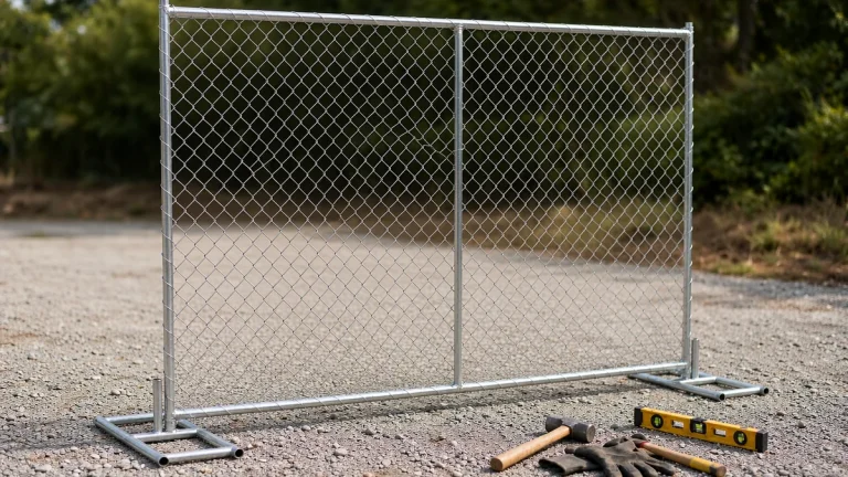
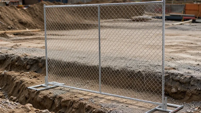
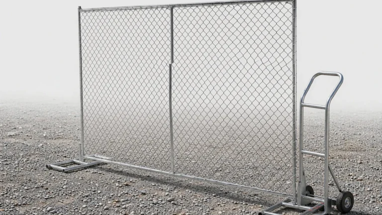
To stop temporary fence feet from moving, seat each base on firm, level support, secure the panels with the correct connectors, and fit the ballast, braces or anchors specified for that fence system and site. If a foot slides, improve its resistance to sideways movement. If it tips, correct the support arrangement. If it sinks, spread the load or improve the ground. If it rocks, fix its seating before adding weight.
There is no universal number of sandbags or blocks per panel. The required support depends on panel dimensions, wind exposure, screening, ground conditions and the complete assembly. WorkSafe Victoria’s construction-site guidance calls for proprietary fencing to be installed to the manufacturer’s specifications and remain stable under anticipated forces, including strong winds. Construction site security fencing
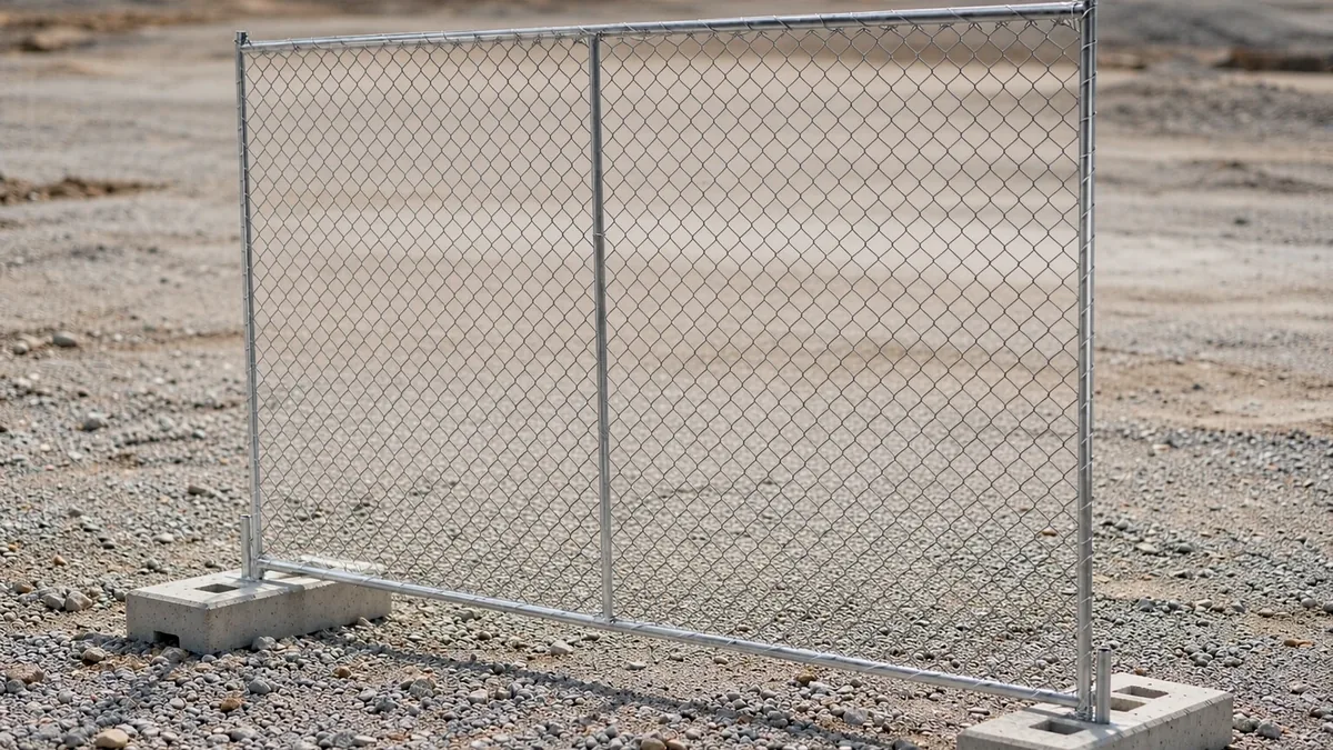
| Movement | What to inspect | What to correct |
|---|---|---|
| Slides sideways | Movement across the ground, displaced ballast and loose connections | Restore the specified ballast and connections; use compatible anchors where the design requires them |
| Tips over | One edge lifts while the panel leans; a brace or its fixing may be missing | Restore the designed ballast position, braces and anchor connections |
| Sinks | Depressions, ruts, ponding or soil squeezing out around a foot | Use suitable load-spreading support, improve the bearing area or relocate the line |
| Rocks | Uneven contact beneath the base, a bent foot or an incompletely seated socket | Re-seat or replace the component and provide even support beneath its intended bearing surfaces |
Inspect the feet and connections first
Check the actual foot-to-ground contact and the panel-to-foot connection. Clearance beneath the middle of a panel does not establish whether its feet are seated: some systems have intentional bottom clearance. There is no universal finger-width test for correct installation.
Look along the whole run for rotated bases, leaning panels, missing clamps and displaced ballast. Check end panels, corners and gate posts as well as the foot that first caught your attention. ASTM F3342-19 calls for temporary construction fencing to form a continuous barrier, with panel sections securely attached together or to a supporting post using a steel fitting that provides a positive connection. F3342 19
Use the specified connector type, location and tightening instructions. Do not assume a clamped line automatically shares loads equally between all feet. The connectors, braces and their supports must be suitable for the arrangement. Keep people clear of a visibly unstable section and have it secured before examining loose parts; a hand push is not a wind-load test.
Operate the gate only when its supports are stable. Look for dragging, loose hinges, a moving latch post and uncontrolled swinging. A slamming gate produces an impact whose size cannot be inferred from its weight alone. HSE guidance says gates should be secured whether open or closed to prevent uncontrolled movement. Hsg151.htm Haisen’s gate measurement guide covers opening width, clearance and swing direction when setting out the entrance.
Prepare a stable bearing surface
Remove loose debris beneath the base and provide a firm, even bearing area. On gravel, correct loose or uneven material rather than balancing a foot on individual stones. On a slope, use the supplier’s approved arrangement for changes in level; do not twist the panel into place or prop a base on loose bricks or offcuts.
Deal with water collecting around feet and with runoff washing support away. Recheck soft ground after rain. Rutgers Extension explains that soil moisture affects compaction assessments and that dry soil bears weight better than moist or wet soil. Its lawn penetrometer and wire-flag tests assess landscape compaction, not the allowable bearing pressure or anchor capacity of a fence installation. Fs1313
Appearance alone cannot give you a load rating: wet-looking soil does not necessarily have zero capacity, and grass does not automatically make a location unusable. If the surface cannot support the assembly without settlement, the options include a suitable spreader, ground preparation or a different location. Do not transfer a manufactured-home compaction percentage or drainage gradient directly into a temporary-fence specification.
Before staking, probing or excavating, arrange the applicable utility checks. In the United States, contact 811 a few business days before digging and follow the local process; fence installation is included. Www.call811.com Other countries have their own utility-location services.
Fix the four types of movement
Stop it sliding
Ballast can increase the downward force on a foot and therefore its frictional resistance, but the result depends on the contact surface. Loose grit, an unsuitable pad or a moving base can defeat the arrangement. Keep the intended bearing surfaces clean and use only pads or anti-slip accessories compatible with the system.
If the design uses ground anchors, confirm the anchor type, installation depth, load direction and required capacity for the actual soil. Weak ground can also provide poor anchor resistance, so driving a stake into soft soil is not an automatic substitute for ballast.
Soil-probe torque is not an anchor’s allowable sideways load or pullout rating. HUD’s manufactured-home installation table describes torque testing as an aid to evaluating soil holding capacity and requires the probe shaft to suit the full anchor depth. Those inch-pound readings cannot be read as pounds of fence resistance, and the HUD table is not a temporary-fence anchoring schedule. Section 3285.202
Stop it tipping over
Check both the amount of ballast and where it bears on the assembly. A block sitting beside a foot does not restrain it unless a designed base or connection transfers the load. Use the specified ballast trays, bags, blocks and retainers; keep them clear of gates and pedestrian routes.
Ballast resists tipping through its weight and its horizontal distance from the potential tipping edge. Measure that distance from the tipping edge to the ballast’s centre of gravity, not simply from the panel centreline.
The following arithmetic illustrates leverage only. It assumes a 35 lb ballast weight is securely coupled to a sufficiently rigid base, with its centre of gravity on the resisting side of one chosen tipping edge. It does not establish the wind load, required ballast quantity, connection strength or stability of a real fence.
| Horizontal distance from tipping edge | Calculation | Resisting moment |
|---|---|---|
| 12 in (1 ft) | 35 lb × 1 ft | 35 lb·ft |
| 18 in (1.5 ft) | 35 lb × 1.5 ft | 52.5 lb·ft |
| 24 in (2 ft) | 35 lb × 2 ft | 70 lb·ft |
These distances are example inputs, not installation recommendations. Moving ballast outward helps only if the base and connection can carry it and the arrangement remains safe. Wind can reverse direction, so placing weight for one direction alone does not establish stability in the other.
Fit braces at the locations and spacing given in the support plan, including any specified end, corner and gate supports. A brace needs a secure panel connection and a suitable ground connection or ballasted support. Do not attach it to the mesh or assume a general-purpose fence post is an approved brace anchor.
Reassess the support plan before adding privacy mesh, banners or signs. WorkSafe Victoria warns that coverings may require additional support for wind loading. Construction site security fencing ASTM F3342-19 likewise warns that wind screening forms a solid barrier and calls for screened fencing to be researched and designed to support the wind load. F3342 19 Neither source gives a universal block count for your panels.
Stop it sinking
Adding ballast to a sinking foot can make settlement worse. Check the total load and the effective contact area, then use a suitable load-spreading base or improve the bearing support. A pad must be stiff enough to distribute the load, supported beneath its working area and stable against sliding.
For an arithmetic example, a 35 lb load distributed uniformly over a 6 × 6 in contact area produces 140 lb/ft². The same load distributed over a 24 × 24 in area produces 8.75 lb/ft², one-sixteenth as much. This comparison excludes the fence weight, other ballast and overturning effects; the full assembly must be assessed, and actual pressure may be uneven.
A large pad does not solve an unsupported void or deeper unstable fill. USDA NRCS guidance explains that bearing capacity depends on the soil and footing conditions, with settlement also relevant to the allowable pressure. 31760.pdf Where the ground continues to deform, have the support arrangement reassessed rather than stacking more material onto it.
Stop it rocking
Restore even contact beneath the base’s intended bearing surfaces and fully seat the panel in its socket. Check for trapped stones, a bent base, damaged welds and incompatible parts. Replace damaged components; extra weight does not repair a distorted foot.
Keep base seating separate from containment clearance. Once the base is supported correctly, check the gap beneath the panel for its intended use. HSE advises keeping gaps beneath construction-site fences and gates as small as possible to prevent access. Hsg151.htm
Choose support for the surface
| Surface | Practical approach | What needs confirmation |
|---|---|---|
| Grass or firm soil | Check for local softness, roots, slopes and settlement; use compatible bearing pads where specified | Whether the ground can support the complete assembly, particularly after rain |
| Soft soil or recent fill | Improve or relocate the bearing area, or use a project-specific support arrangement | Both bearing capacity and anchor capacity; neither follows from appearance alone |
| Loose gravel | Provide a firm, even support area without isolated stones under the base | Whether the base or pad can slide, rock or wash out |
| Asphalt | Use a compatible non-penetrating system where required, with appropriate load spreading | Pavement condition, surface protection and a verified anchoring method if penetration is proposed |
| Concrete | Use the specified ballasted arrangement or concrete anchors selected for the substrate | Slab thickness, condition, reinforcement or services, edge distances and permission to drill |
Do not assume the road base beneath asphalt will hold an ordinary driven stake. If drilling or staking is prohibited, the solution is a suitable non-penetrating fence system, not improvised weights. Haisen’s panel size and site-layout guide helps identify the surface, panel layout and access constraints to give the supplier.
Record what changed on site
Use a short installation record so the next inspection can distinguish a loose connector from ground movement. The following is a suggested record format, not a report of a tested installation.
- Identify the location: panel or bay number, gate or corner, surface and date.
- Record the symptom: sliding, tipping, sinking or rocking. Photograph the base and nearby connections from a safe position.
- Check the specified assembly: foot type, connectors, ballast quantity and position, braces, anchors and any screening.
- Record the correction: which component was re-seated or replaced, what ground support changed, and which supplier instruction or support drawing was followed.
- Record who checked the completed work and when it needs reinspection. Keep any load-test results separate from visual checks.
For example, if a base settles after rain, record the depression and ground condition before changing the ballast. If ballast has moved but the ground remains level, record its displacement and inspect the retainer. These are diagnostic comparisons to make on your own site, not evidence that a particular installation has passed a load test.
Inspect before use and after wind, heavy rain, impact, relocation or a change in screening. Look for fresh settlement, moved ballast, loose connections and damaged parts. Haisen’s storage and transport guide also covers checks before reused panels and detachable feet return to service.
Keep animal and public access in mind
A dog can push, jump, chew or dig, so a stationary foot alone does not make a panel suitable for a dog run. Body weight does not equal sideways fence force: a 70 lb dog does not automatically apply 70 lb horizontally. Avoid sizing ballast from an animal’s weight.
For facilities covered by US animal-welfare regulations, dog and cat primary enclosures must be structurally sound, maintained in good repair, contain the animals securely and have no injurious sharp points or edges. This is a regulated-facility requirement, not a blanket rule for every private yard. Section 3.6 Check gaps, mesh, latches and reachable hardware as well as the feet when considering temporary fence panels for dog runs.
Keep supports out of access routes where possible. HSE says feet projecting into pedestrian areas should be highlighted to avoid tripping hazards. Hsg151.htm Visibility does not make an obstructed route acceptable. For expected crowd pressure, use an arrangement designed for that purpose; wind stability alone does not establish crowd-load capacity. The distinction between event fencing and crowd-control barriers matters when selecting equipment.
Get the support specification before ordering
Give the supplier the panel height and width, run lengths, corners, gates, ground conditions, exposure and planned screening. Ask for the compatible feet, connector details, ballast quantities and positions, brace layout, anchor requirements and applicable wind limits in writing. Haisen’s installation planning guide provides a way to organize those details.
Haisen’s Canadian-style temporary fence product page lists nominal 6 × 8, 6 × 9.5 and 6 × 10 ft panels, 25 × 25 or 30 × 30 mm outer frames, 3.0, 3.5 or 3.8 mm wire, and hot-dip galvanized or powder-coated finishes. These are product specifications, not wind ratings. The page reviewed does not provide a quantified wind rating or a ballast schedule for a complete installation.
Use a project-specific design when the supplier’s documented arrangement does not cover the site, especially with screening, unusual exposure, unstable ground or expected crowd loads. ASTM is a standards organization, not a regulator; the guidance cited here comes from different jurisdictions. Apply the governing local requirements and a compatible manufacturer or project specification.
Quick answers
How many sandbags does each panel need?
Use the quantity, filled weight, placement and restraint specified for the complete fence arrangement. Counting bags without knowing their weight or how they connect to the base does not establish stability. Ask the supplier for the schedule rather than using a generic bags-per-panel rule.
Do all temporary fence feet need anchors?
No. Some systems use a designed ballasted arrangement without penetrating the ground. Others need anchors and braces. Firm ground alone does not establish that an unanchored panel is stable; the complete system must suit its expected loads.
Can I add privacy screening to a stable fence?
Only after confirming the support arrangement for the screened condition. A fence that stands securely as open mesh may need different ballast, braces or anchors with a covering. WorkSafe Victoria specifically flags coverings as a reason additional wind support may be needed. Construction site security fencing
What to check before leaving the line
Feet can slide, tip, sink or rock. Confirm that the bases are supported, the panels are connected, the specified ballast and braces are in place, and the gates work without disturbing their supports. Record the installation and recheck it after conditions change. More weight helps only when the base, ground and connections can carry it.
Planning a fence line that has to take weather, animals and people? Send the panel height, the run length, the surface under the feet and the site wind speed, and ask for the support arrangement in writing before the panels go up.
References
WorkSafe Victoria, Construction site security fencing (page reviewed 28/07/2022): https://www.worksafe.vic.gov.au/construction-site-security-fencing
ASTM International, ASTM F3342-19, Standard Guide for Temporary Fence Applications for Construction Sites (Active, last updated 2019-05-23): ASTM F3342 Standard Guide for Temporary Fence Applications for Construction Sites
UK Health and Safety Executive, HSG151 Protecting the public: Your next move (2009): https://www.hse.gov.uk/pubns/books/hsg151.htm
Rutgers University NJAES Cooperative Extension, FS1313 Assessing and Addressing Soil Compaction in Your Yard (January 2020): https://njaes.rutgers.edu/fs1313/
811, Common Ground Alliance, national before-you-dig service: https://www.call811.com/
US Department of Housing and Urban Development, 24 CFR 3285.202 Soil classifications and bearing capacity (eCFR, Title 24 up to date as of 10/22/2026): https://www.ecfr.gov/current/title-24/section-3285.202
US Department of Agriculture, Natural Resources Conservation Service, National Engineering Handbook, Part 210, Chapter 4 Elementary Soils Engineering (210-650-H, 2nd Ed., Feb 2021), section 650-4.4E Bearing Capacity: https://directives.nrcs.usda.gov/sites/default/files2/1712930846/31760.pdf
US Department of Agriculture, Animal and Plant Health Inspection Service, 9 CFR 3.6 Primary enclosures (eCFR, Title 9 up to date as of 10/22/2026): https://www.ecfr.gov/current/title-9/chapter-I/subchapter-A/part-3/subpart-A/section-3.6